iPhone 18 Pro Teardown Analysis: How a Smaller Dynamic Island Changes Repairability
How a Smaller Dynamic Island Changes Repairability
A smaller Dynamic Island may look like a simple reduction in the area occupied at the top of the screen. In the teardown, however, the change also affects the display’s pixel arrangement, infrared camera position and front camera flex cables. The device also shows a revised logic board, a larger cooling structure and changes to the battery connection.
For repair businesses and parts buyers, the key concerns are access and compatibility. The display and infrared camera require closer optical coordination, while access to the NAND flash and power ICs reportedly requires separating the logic board layers. The following teardown analysis looks at these changes alongside the disassembly sequence.
1. Opening the Device
The teardown unit shows a weight of 209.3 grams. Disassembly begins from the screen side: after the device is powered off, the bottom pentalobe screws are removed and heat is applied to soften the perimeter adhesive. A suction tool creates an opening, and an opening pick is used to separate the screen around the edges.
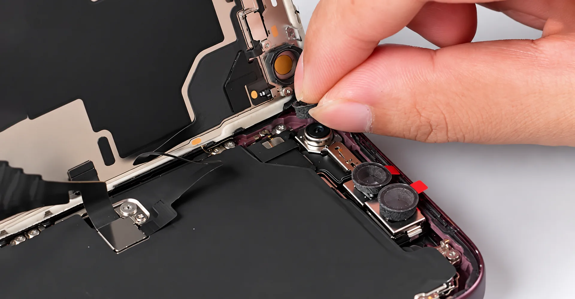
Before removing the display, the technician protects the front camera module with foam, removes the battery connector bracket and disconnects the battery. The display bracket is then removed, followed by the display and front sensor cables. The screen remains connected until these cables are released.
2. The Display and Infrared Camera Change Together
2.1 Why the Dynamic Island Is Smaller
The smaller Dynamic Island is linked to an infrared camera positioned beneath the display. The teardown also shows a magnified view of the corresponding screen area, where the pixel arrangement is adjusted to allow infrared light to pass through.


According to the teardown, the infrared camera opening has moved toward a corner of the screen, freeing space in the Dynamic Island region. The visible opening and the sensing hardware are not the same thing; reducing the front-facing area does not mean the associated sensor has been removed.
The key change is the coordination between the display’s infrared-transmitting region and the camera position underneath it. The smaller Dynamic Island therefore comes from changes to both the display and camera layout, rather than from a smaller cutout alone.
3. Replacement Displays and the Front Camera Module
3.1 Optical Compatibility Matters
The teardown highlights a new consideration for aftermarket display design. From a repair and sourcing perspective, an iPhone replacement screen must do more than display an image and register touch; the relevant screen area also needs to match the infrared camera’s position and optical requirements.
The teardown does not include aftermarket-panel comparisons, infrared-transmission measurements, recognition success rates or calibration data. The structural change therefore highlights a compatibility requirement rather than proving that a specific replacement display will fail.
The display flex cable is also shown without adhesive retention, indicating a change in how the cable is secured.
3.2 Three Separate Flex Cables
After removing the front camera module, the technician compares the infrared camera position with the previous arrangement. The camera sits farther from the front camera, creating the bridged layout described in the teardown. The module uses three separate flex cables.
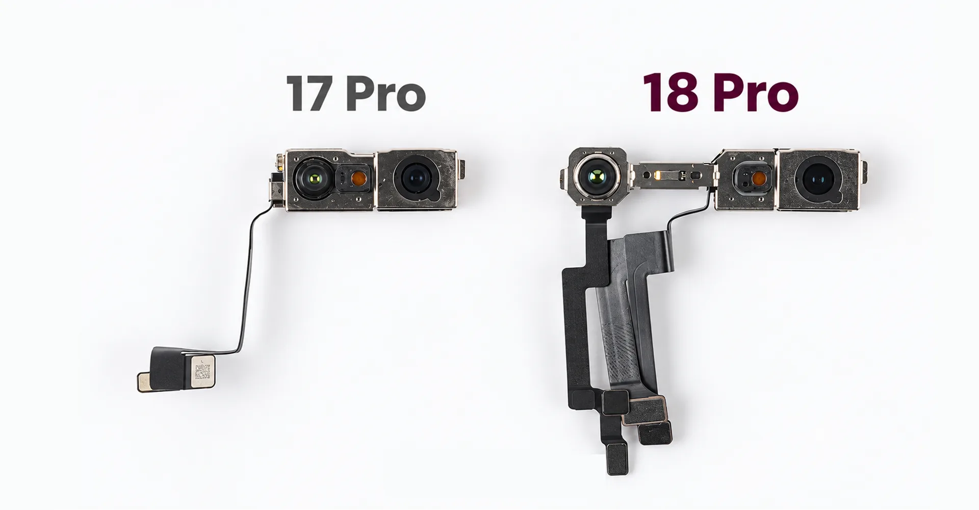
For repair work, the important point is the distribution of the module’s components and connections. These changes need to be considered together with the revised display region. The teardown does not include Face ID pairing, calibration or a completed replacement test.
4. Logic Board Removal and the Thermal Interface
4.1 A Connection Remains Behind the Board
The rear camera module, front camera module and upper speaker are removed before the logic board is released. After the screws and accessible cables are disconnected, the technician gently lifts and turns the board. The wireless charging coil cable bracket and connection must then be released before the board can be removed.
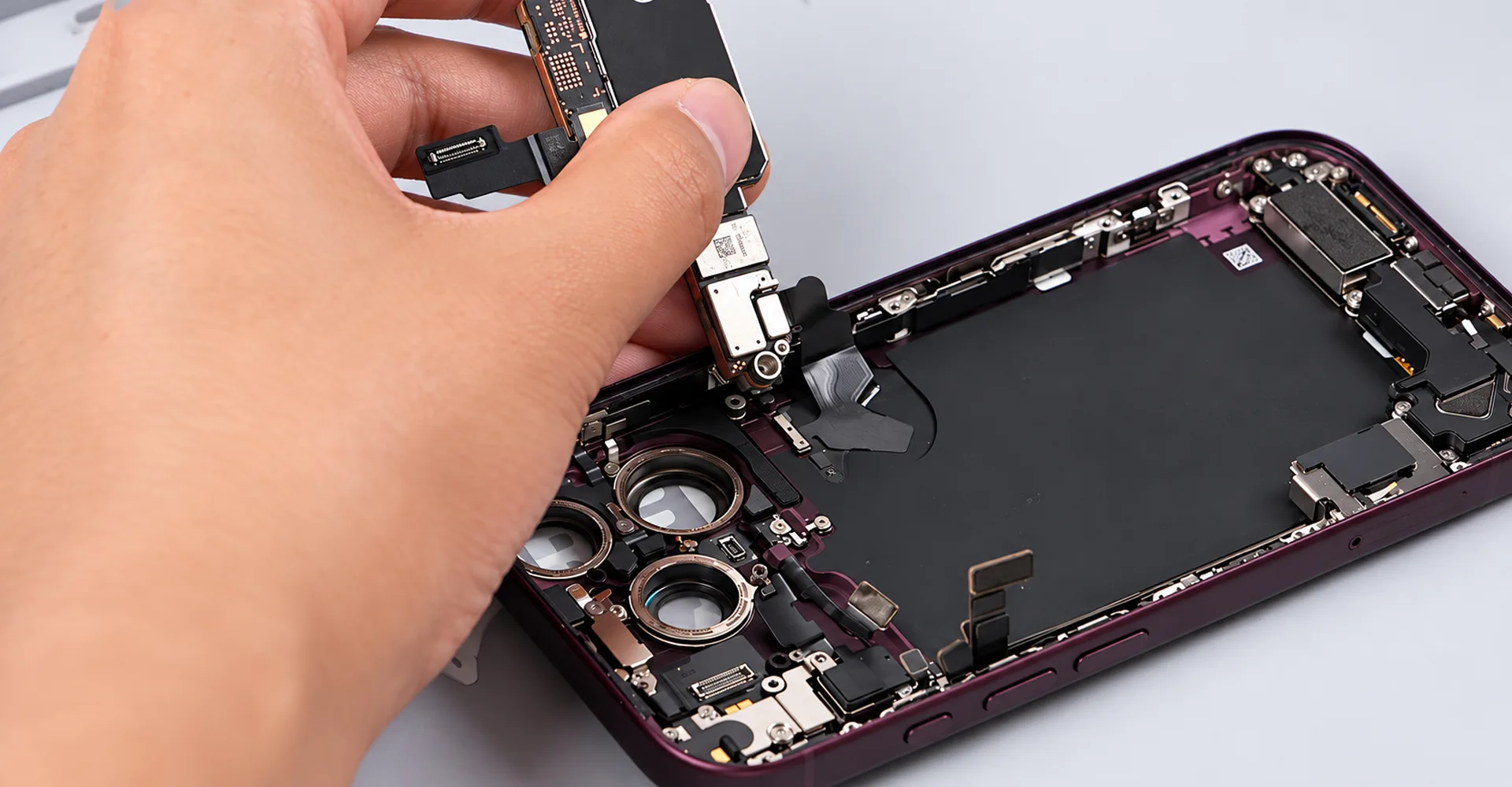
The teardown also shows slightly wider and thicker cables in several areas, together with longer Wi-Fi and flash cables, indicating changes in internal routing.
4.2 A20 Pro Moves to the Surface
According to the teardown, the A20 Pro chip is positioned on the surface of the logic board. A thermal pad made from a new material couples it to the vapor chamber.
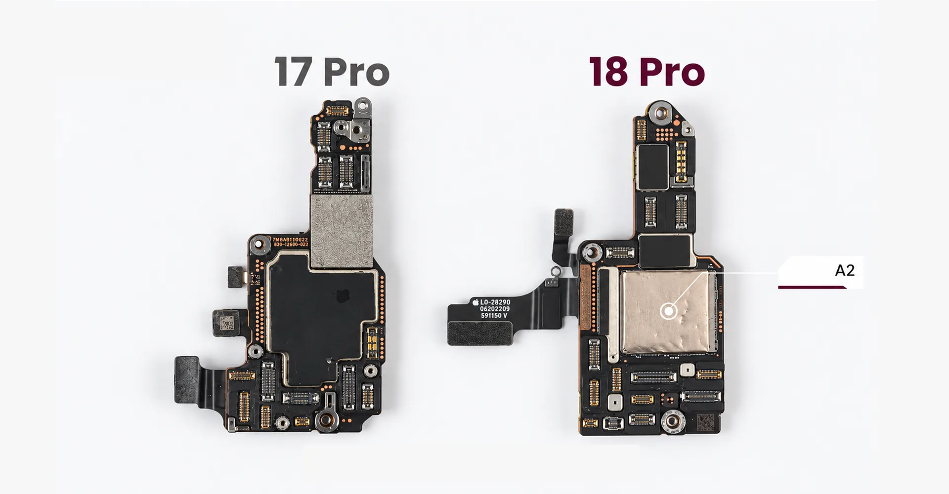
This changes the heat-transfer path between the processor and vapor chamber. During reassembly, the thermal interface needs to be restored correctly. The teardown does not specify the thermal-pad material, thickness or replacement standard.
5. Exposed Components and Inaccessible Chips
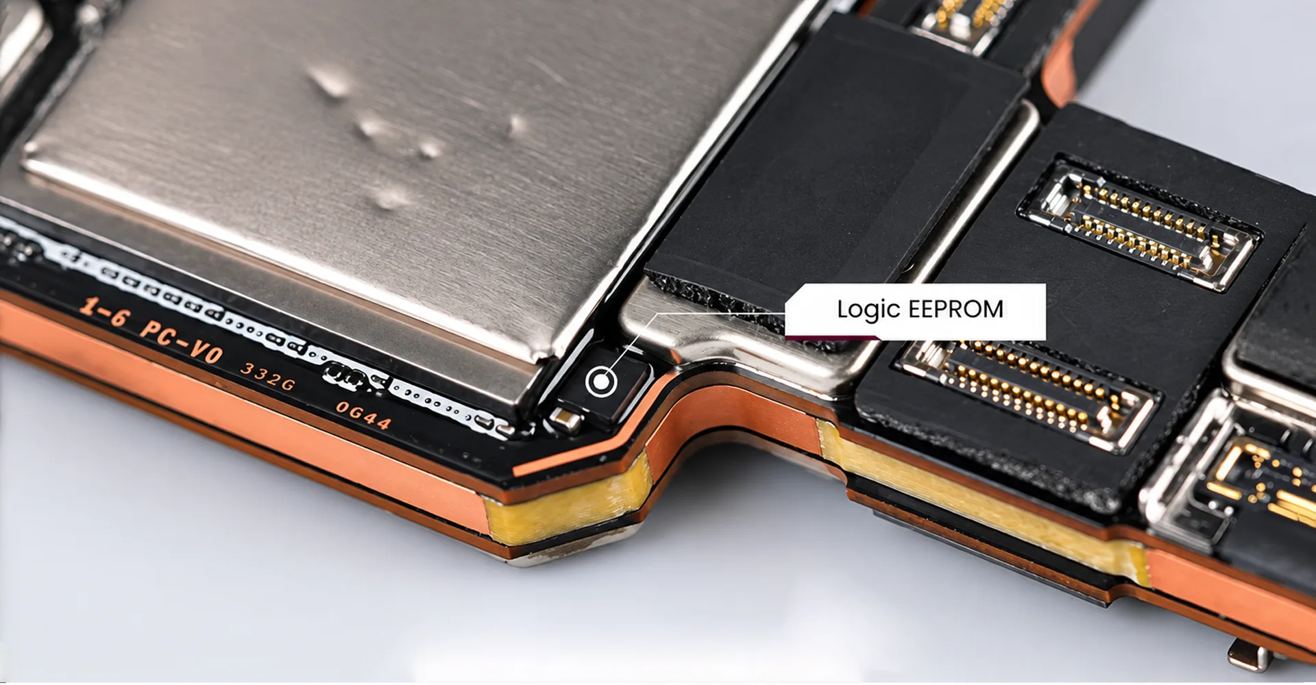
5.1 The Logic EEPROM Has No Shield
The surface-mounted logic EEPROM is shown without a protective shield, leaving the component more exposed during handling and board-level service.
5.2 NAND and Power IC Repairs Require Board Separation
One of the clearest board-level access changes is the placement of the NAND flash and power ICs between the logic board layers. According to the teardown, technicians must separate those layers before these components can be reached.
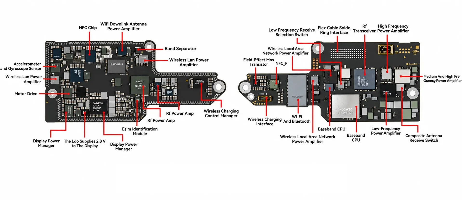
This is different from the exposed EEPROM. The EEPROM issue concerns physical protection, while the NAND and power IC layout concerns access to components enclosed within the board assembly. Layer separation adds another board-level operation before the target chip can be serviced.
The teardown identifies this access challenge but does not show the complete board separation, chip replacement and board rejoining process.
6. Rear Cameras and the Lower Assemblies
6.1 A Larger Main Camera
After releasing the relevant vapor chamber fasteners, the technician removes the rear camera module. The teardown describes a larger Fusion main camera, support for variable aperture and a changed cable layout. A 4IP screwdriver is used for the vapor chamber screws shown in this part of the disassembly.
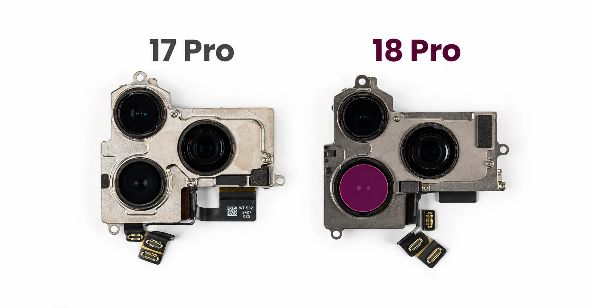
For repair work, the most relevant changes are the module size and cable arrangement. The teardown does not include internal camera repair or post-replacement calibration.
6.2 Removing the Remaining Modules
After the logic board is removed, the sequence continues through the flash, LiDAR, SIM tray and SIM reader. Removing the tray does not release the reader itself; the reader remains secured and connected by a cable.
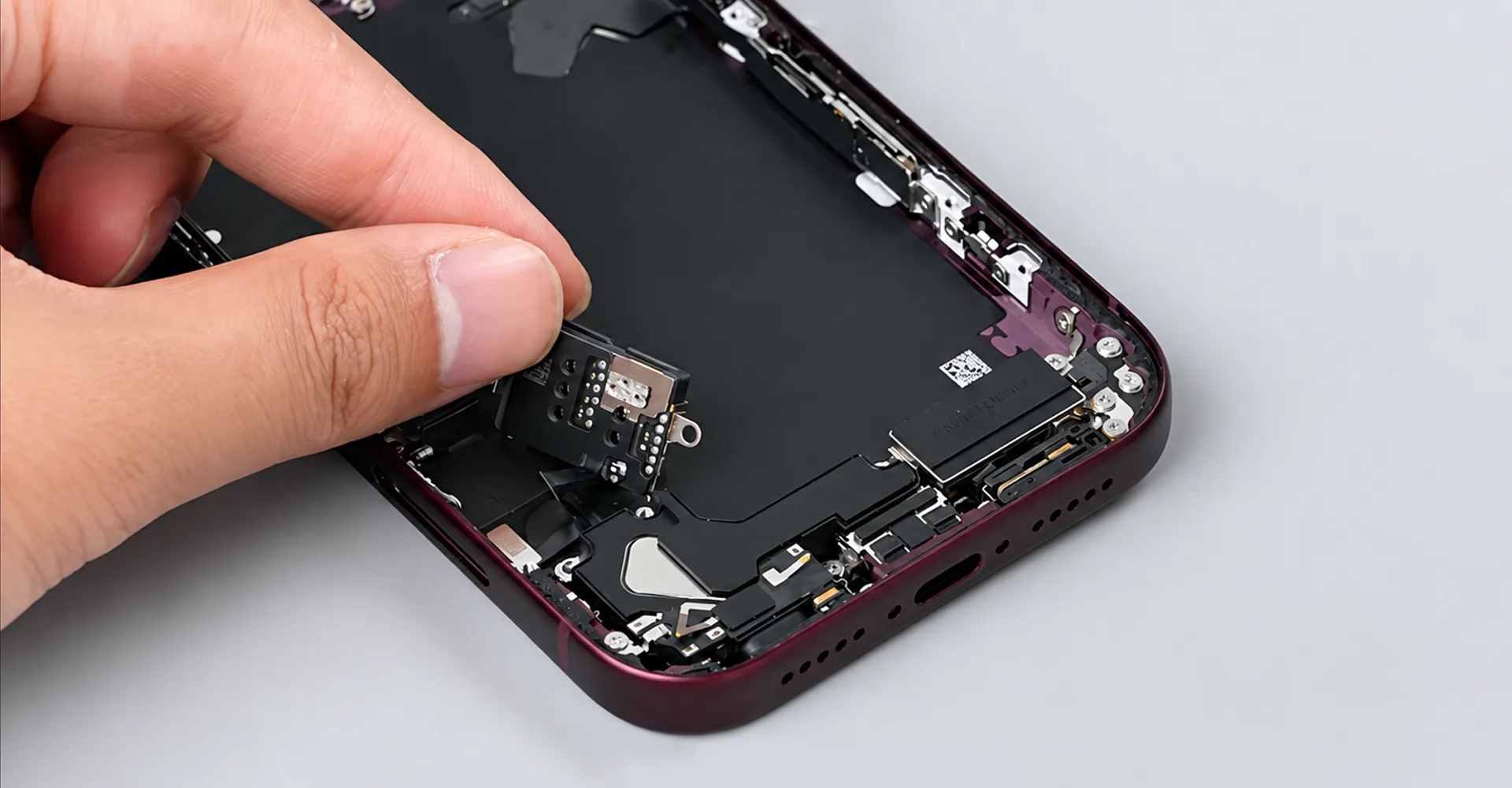
The technician then removes the lower speaker, charging-port fasteners and Taptic Engine, completing the remaining lower-assembly disassembly. The SIM hardware shown also identifies this teardown unit as a physical-SIM configuration.
7. Charging Port Changes and Battery Release
7.1 One Charging Port Cable Instead of Two
The charging-port section shows the technician releasing the flex-cable fasteners, softening adhesive and gradually loosening the charging-port assembly before removing it. The microphone is removed afterward.
In the comparison that follows, the teardown describes the charging-port arrangement as having one cable instead of the previous two.
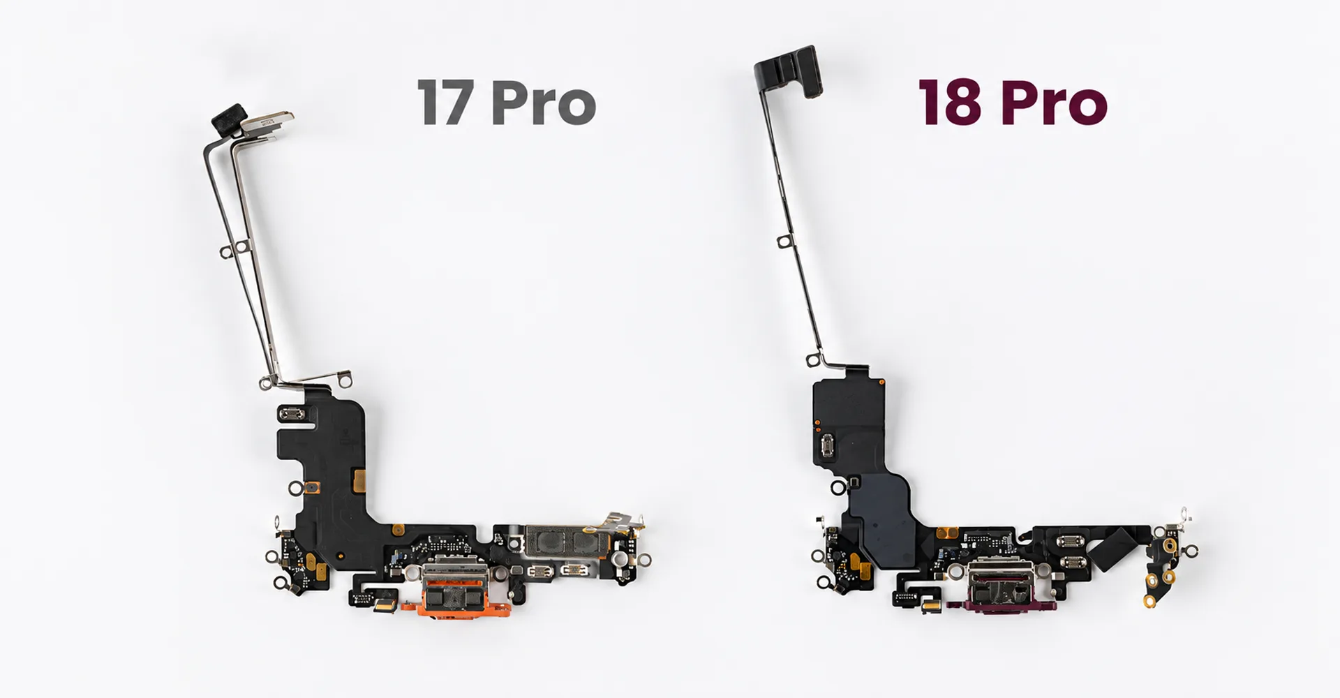
The move from two cables to one is a clear layout change. On its own, however, it does not establish that the charging port is easier to repair, more durable or less expensive to replace.
7.2 Electrically Released Battery Adhesive
The battery-removal section demonstrates adhesive release using an external power source. The teardown specifies 9V DC and shows the contact points used in the demonstration.
Because the teardown does not provide complete current limits, timing requirements, model variations or abnormal-condition guidance, this should be treated as an observed removal method rather than a complete service procedure.
8. Battery Capacity and Connection Design
8.1 The Capacity Figure Applies to the Physical SIM Version
The teardown describes a slightly larger iPhone battery than the iPhone 17 Pro’s and gives a capacity of 4,056 mAh, approximately 1.7% higher. The comparison frame explicitly labels this as the Physical SIM Version.
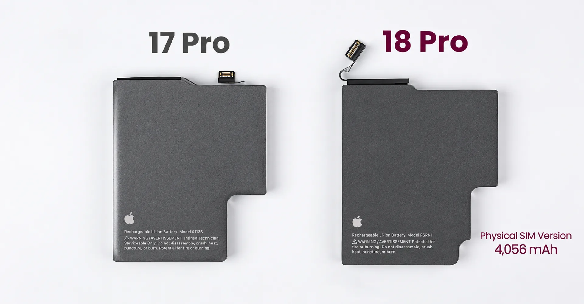
That qualification is important: the 4,056 mAh figure applies to the physical-SIM version shown and should not be treated as a universal capacity for every regional or hardware configuration.
8.2 A Larger Connector and Multilayer Flex
The teardown also identifies a larger battery connector, a multilayer flex cable and a change of battery supplier, although the supplier is not named.
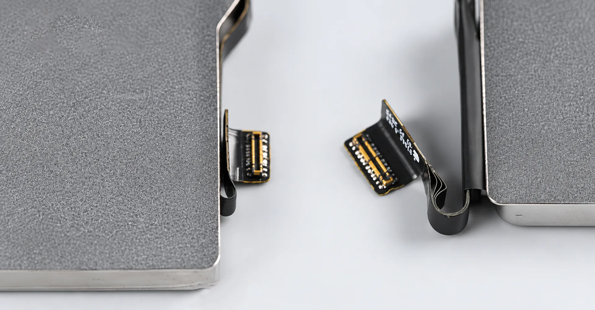
The teardown suggests that the larger connector may support 50W fast charging, but this remains speculative. Connector size alone does not confirm charging power, and no charging curve or power measurement is shown.
For repair analysis, the confirmed structural points are the changed connector and multilayer flex. The 50W figure should therefore be treated as a possibility rather than a confirmed specification.
9. A Larger Vapor Chamber and a Familiar Enclosure
9.1 Cooling Structure Versus Measured Performance
The vapor chamber is shown as substantially larger, working with the surface-positioned A20 Pro and revised thermal pad to create a different heat-transfer path. The teardown presents these changes as the basis for expected cooling improvements.
The narration also relays a claim that the vapor chamber area is about three times larger than before. The teardown itself does not provide a separate source or measurement for that figure.
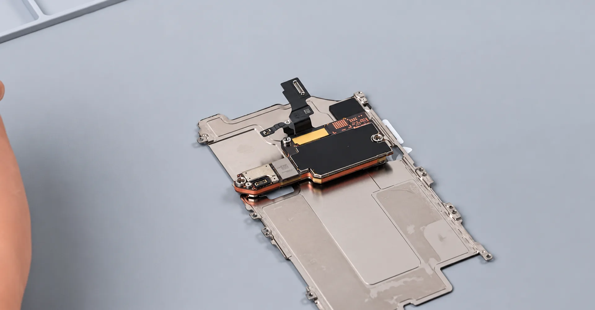
A larger vapor chamber area should not be interpreted as three times the cooling performance. No temperature measurements or sustained-load thermal tests are included in the teardown.
For technicians, the more immediate consideration is the structural relationship between the board, thermal interface and vapor chamber. Correct contact across these parts remains important during reassembly.
9.2 Frame and Rear Cover
The closing section reports no major structural change to the frame or rear cover. It describes a more closely color-matched combination of aluminum and glass on the back.
These enclosure changes complete the overall comparison, while the more repair-sensitive areas remain the display and infrared-camera relationship, exposed board components and access to chips inside the logic board.
10. Repair Implications at a Glance
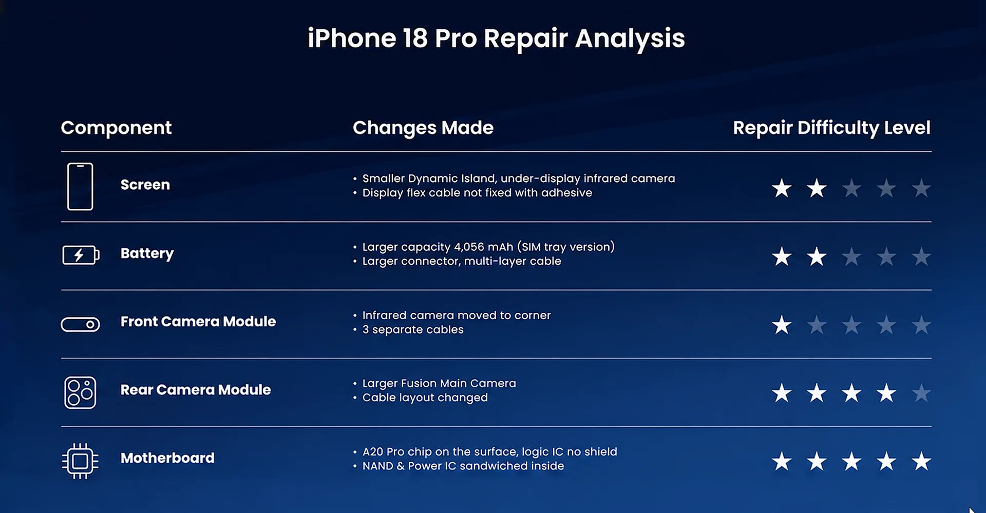
The table below summarizes the structural changes shown in the teardown and the main repair considerations associated with each one.
| Component | Change described | Repair consideration |
| Display | Smaller Dynamic Island and revised infrared region | Replacement-screen optical compatibility becomes more important |
| Front camera | Relocated infrared camera and three flex cables | Sensor layout and connections are more complex |
| Board surface | Surface-positioned A20 Pro and unshielded EEPROM | Thermal contact and exposed-component protection require attention |
| Board interior | NAND and power ICs between layers | Access reportedly requires board-layer separation |
| Rear camera | Larger main camera and variable aperture | Module size and cable layout change; calibration is not shown |
| Charging port | One cable instead of two | Simpler cable layout, but easier repair is not established |
| Battery | 4,056 mAh physical-SIM version and revised flex | Capacity is configuration-specific; 50W remains unconfirmed |
| Vapor chamber | Larger area and revised thermal path | Larger area does not quantify actual cooling gain |
10.1 What the Teardown Establishes
The smaller Dynamic Island increases the importance of coordination between the display and infrared camera. The revised logic board creates a different challenge, with NAND and power IC access reportedly requiring board-layer separation. These are separate repair considerations and should be evaluated independently.
For professional repair businesses and parts buyers, the practical questions are which components can be reached, which connections have changed and which interfaces must be restored during reassembly. Replacement-screen compatibility, actual charging power, cooling gains and complete repair outcomes are not tested in the teardown.
For B2B sourcing related to these repair categories, see WOSENTE’s iPhone Screens, iPhone Batteries, Camera Modules, Charging Port Assemblies and Other Phone Repair Parts. For bulk purchasing, review the Quality Control and Wholesale Business pages, or Contact Us for model availability and quotation support.